+7 (8482) 20-81-45 Reception
+7 (8482) 20-85-90 Sales dept
г. Тольятти, ул. Громовой 33-А а/я 1839
+7 (8482) 20-81-45 Reception
+7 (8482) 20-85-90 Sales dept
г. Тольятти, ул. Громовой 33-А а/я 1839

Counter-flow ion-exchange filters (FIPr) are used in water softening and desalting schemes at chemical water treatment units of thermal power plants, boilers and industrial enterprises.
Equipment parameters:
 Price -
on request
Price -
on request
 Warranty -
24 months
Warranty -
24 months
 Delivery -
Worldwide
Delivery -
Worldwide


Description


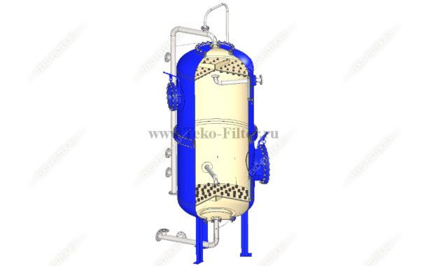
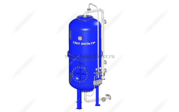
IIon-exchange column for water treatment Fipr (FIPr)
Purpose. Counter-flow ion-exchange filter (FIPr) is designed to remove hardness cations (Ca2+ and Mg2+) from the incoming flow during the sodium/hydrogen cation exchange, as well as sulfate, chloride and nitrate anions during the desalting of natural waters. The resulting softened or primarily desalted water is most often used as makeup for steam boilers (low, medium and high pressure steam generation), hot-water boilers, heating networks. Less often, water after ion-exchange treatment is used in various industrial technologies.
Ion-exchange materials of natural and artificial origin, such as cationites and anionites, are used as the filtering media in ion-exchange filters.
Design description. Counter-flow ion-exchange filter FIPr consists of:
The FIPr filter housing is cylindrical, welded of sheet steel, with welded elliptical stamped bottoms. Three supports are welded to the bottom for mounting the filter on the foundation.
The difference between a counter-flow ionization system and a parallel-flow one is that the regeneration of the filter material is performed in the direction opposite to the flow of the treated water. Before leaving the filter, the treated water comes into contact with well-regenerated ionite layers, which provides a deep ion exchange, and improves the quality of the resulting water.
For counter-flow filters with mechanical clamping of ionite, upper collection-distribution device and lower collection-distribution device of the "False bottom" type are used with plastic or stainless caps FEL.
For FIPr filters with hydraulic clamping of ionite, upper collection-distribution device of the "perforated pipes" type (or "cup in cup" type) is used. Moreover, for the operation of an ionite counter-flow filter with hydraulic clamping of the ionite, a medium collection-distribution device (USSR) and a horizontal lower collection-distribution device of the "duplicating" type are provided.
Operation principle. The operation cycle of the FIPr ion-exchange counter-flow filter consists of the following stages:
The operation cycle of the FIPr filter ends at the cations (or anions) breakthrough, which is determined by the technological regulations, i.e. the depletion of the ion-exchange capacity of the filtering medium.
Operation principle of FIPr water softening filter (with mechanical clamping of ionite and upward regeneration flow).
The incoming flow of clarified water under pressure enters the FIPr filter and is evenly distributed through the slot caps of the upper "false bottom", passes downwards through a layer of inert material and then through a layer of filtering medium. The hardness cations are kept in the grains of the material, and the sodium cations move into the filtrate, which is discharged from the filter through the lower "false bottom" to the collector.
After the cationite capacity is depleted (set by analytical control of the hardness cation breakthrough), the filter stops and switches to the cationite regeneration mode (restoring the exchange capacity). For the regeneration process a flow of softened water is supplied upwards to the FIPr filter to bring up and press the entire layer of the ionite (2-5 minutes), after which comes pre-prepared regenerant solution (10-15% salt solution) and the pressing and compaction flow is stopped. After a certain volume of regeneration solution is supplied, its supply is stopped and the flow of softened water comes for washing the cationite. The volume of the washing flow is gradually reduced, providing the "layer-by-layer" deposition of ionite in the filter. Pressing water, waste regeneration solution, and washing water are discharged into the drainage.
After washing and restoring the exchange capacity of the cationite, the filter is switched on or remains in standby mode. Right after the filter is switched on, the first portion of the filtrate is discharged into the drainage and analytical control is performed. After getting the regulatory figures for the treated water, the FIPr filter is connected to the treated water collector.
Operation principle of FIPr water softening filter (with mechanical clamping of ionite and downward regeneration flow).
The incoming flow of pretreated water under pressure enters the FIPr filter upwards and is evenly distributed through the slot caps of the lower "false bottom", brings up the entire ionite layer and presses it against the layer of inert material, which evenly distributes the flow and hydraulic pressure over the entire surface of the upper "false bottom". The hardness cations are kept in the grains of the material, and the sodium cations move into the filtrate, which is discharged from the filter through the upper "false bottom" to the collector.
After the cationite capacity is depleted (set by analytical control of the hardness cation breakthrough), the filter stops and switches to the cationite regeneration mode (restoring the exchange capacity). The regeneration begins after the complete deposition of ionite in the FIPr filter. The inert material is located as the upper layer above the cationite and is pressed against the upper collection-distribution device. A flow of pre-prepared softened water base regenerant solution (10-15% salt solution) is supplied downwards. After a certain volume of regeneration solution is supplied, its supply is stopped and the flow of softened water comes for washing the cationite. Waste regeneration solution and washing water are discharged into the drainage.
After washing and restoring the exchange capacity of the cationite, the filter is switched on or remains in standby mode. Right after the filter is switched on, the first portion of the filtrate is discharged into the drainage and analytical control is performed. After getting the regulatory figures for the treated water, the FIPr filter is connected to the filtrate collector.
Operation principle of FIPr water softening filter (with hydraulic clamping of ionite).
The incoming flow under pressure enters the FIPr filter, where it passes downwards through a layer of filtering medium. The hardness cations are kept in the grains of the material, and the sodium cations move into the filtrate, which is discharged from the filter through the lower collection-distribution device of the "false bottom" type to the collector.
After the cationite capacity of the upper "blocking layer" is depleted (set by analytical control of the hardness cation breakthrough through the sampling device located under the caps of the middle collection-distribution device), the filter stops and switches to the mode of backwashing and regeneration (restoration of exchange capacity) of the "blocking layer" cationite. For this operation, the FIPr filter inlet and outlet are locked up, and the flow of softened water for backwashing or a pre-prepared regenerant solution (10% salt solution) is supplied upwards to the middle collection-distribution device. After a certain volume of regeneration solution is supplied, its supply is stopped and the flow of softened water comes for washing the cationite. Waste regeneration solution and washing water are discharged into the drainage through the upper collection-distribution device. Intermediate (short) regeneration of the upper layer of cationite allows washing it from mechanical contaminations and restoring the exchange capacity, which in turn provides a better treatment of the lower ionite layers.
After the capacity of the entire volume of cationite is depleted (set by analytical control of the hardness cation breakthrough in the filtrate flow), the filter stops and switches to the full regeneration mode (restoration of full exchange capacity). A flow of pre-prepared softened water base regenerant solution (10-15% salt solution) is supplied upwards through the lower collection-distribution device, and the waste regenerant is discharged through the middle collection-distribution device into the drainage. Some volume of the regenerant or softened water is supplied to FIPr filter downwards for hydraulic clamping of the entire ionite, and the downward flow is discharged through the middle collection-distribution device into the drainage. After a certain volume of regeneration solution is supplied, its supply is stopped and the flow of softened water is comes for washing the entire volume of cationite downwards. Washing water is discharged into the drainage.
After washing and restoring the exchange capacity of the cationite, the filter is switched on or remains in standby mode. Right after the filter is switched on, the first portion of the filtrate is discharged into the drainage and analytical control is performed. After getting the regulatory figures for the treated water, the FIPr filter is connected to the softened water collector.
The upper third part of the FIPr filter with hydraulic clamping of ionite (from the middle collection-distribution device to the upper collection-distribution device) is empty and available to perform the backwashing and washing of the entire cationite right in the housing without using additional, specialized tanks.
Diameter of the housing of manufactured FIPr filters varies from 100 to 3000 mm, capacity of the devices: from 32 to 280 m3 / hour, working pressure: 0.6 MPa.
The outer surface of the filters is coated with standard priming enamel. At the customer’s request, the outer surface can be painted in corporate colors and with the use of special protection against corrosion (ROSNEFT, SIBUR, GAZPROM, LUKOIL, etc.).
|
Filter type
|
Diameter, mm
|
Capacity,
m3/hour |
Operating pressure, MPa
|
Height, mm
|
Filter weight, kg
|
|
FIPr 1,0-0,6
|
1000
|
32
|
0,6
|
3720
|
1650
|
|
FIPr 1,4-0,6
|
1400
|
62
|
0,6
|
4120
|
2600
|
|
FIPr 1,5-0,6
|
1500
|
72
|
0,6
|
4180
|
2800
|
|
FIPr 2,0-0,6
|
2000
|
128
|
0,6
|
4800
|
5100
|
|
FIPr 2,6-0,6
|
2600
|
230
|
0,6
|
5380
|
8100
|
|
FIPr 3,0-0,6
|
3000
|
280
|
0,6
|
5650
|
9650
|
Counter-flow ionization technology with mechanical clamping of ionite has a number of advantages:
Special features of counter-flow ion exchange technology with mechanical clamping of ionite:
Counter-flow ionization technology with hydraulic clamping of ionite has a number of advantages:
Special features of counter-flow ion exchange technology with hydraulic clamping of ionite:
To remodel and switch the operation to the FIPr filter mode with hydraulic clamping of ionite, only the stage I FIPa filter or FSU filter housings are suitable.

Phone:+7 (8482) 20-83-61
Email: info@teko-filter.ru
445056, Russia, Samara region,
Togliatti, Gromovoy str. 33-A, POB 1839
Email info@teko-filter.ru
 445056, Russia,
Samara region, Togliatti,
Gromovoy str.
33-A, POB 1839

 QUESTIONNAIRE
 MAKE A REQUEST